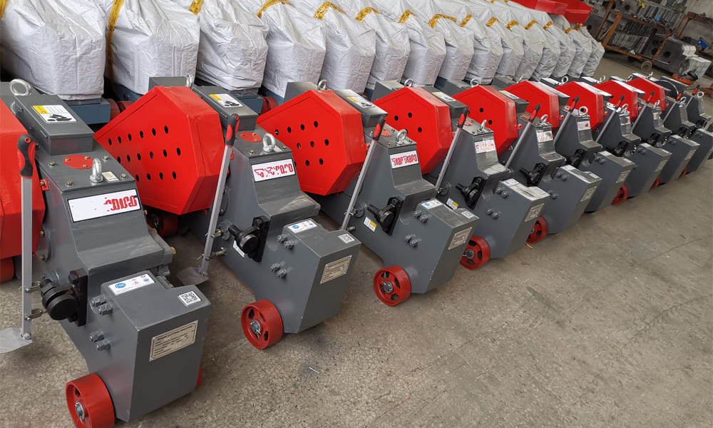
C52 Rebar Cutting Machine is a classic machine for medium and small-sized rebar processing, suitable for cutting φ10-φ52mm hot-rolled plain rebar in construction sites, rebar prefabrication plants and other scenarios. Its core design integrates the advantages of hydraulic transmission and flywheel-type mechanical transmission. Both power versions are designed around the core logic of “efficient power transmission – precise cutter trajectory – stable rebar clamping”. The cutter movement trajectory and power transmission mechanism form differentiated designs due to different transmission methods, while retaining the structural characteristics of Italian models such as compactness, high rigidity and strong operational adaptability. This paper conducts an in-depth analysis from three aspects: core structure, working principle under different power modes, and cutter movement trajectory and power transmission mechanism.
General Core Structure of Italian Model C52 Rebar Cutting Machine
flywheel-type mechanical version of the C52 Rebar Cutting Machine share basic core structures such as machine frame, rebar clamping mechanism, cutter assembly, fixed cutter seat and discharge guide. Differential designs are only made in the power cabin, transmission assembly and moving cutter drive mechanism to adapt to different transmission methods. All structures comply with the modular design and high wear-resistant process requirements of Italian models. The general core structures and their functions are as follows:
- Machine frame: Adopting an integral cast steel integrated frame (some upgraded versions are thick steel plate welding + integral tempering treatment) without splicing gaps. The frame is pre-reserved with a transmission assembly installation cavity and a hydraulic cavity (hydraulic version) inside, and shock-absorbing foot pads and fixing bolt holes at the bottom to ensure the overall rigidity of the machine during cutting operations, avoid cutter offset and rebar slipping caused by vibration. This is one of the core structural characteristics that distinguish Italian models from ordinary models.
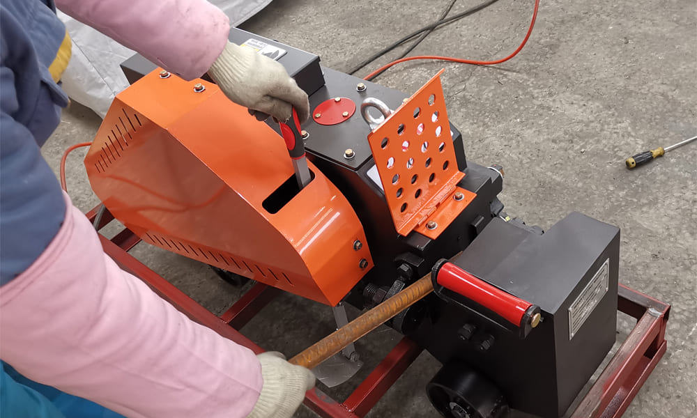
- Rebar clamping mechanism: A manual/semi-automatic linkage V-type clamping seat with a linkage trigger design with the moving cutter drive mechanism (the clamping seat automatically locks when the cutter moves forward). The clamping opening is built with high wear-resistant manganese steel liner to fit and clamp rebars of different diameters, prevent rebar rotation and axial movement during cutting, and ensure a flat cutting surface.
- Cutter assembly: Composed of fixed cutter and movable cutter, both made of high-alloy tool steel in accordance with Italian standards through quenching + tempering treatment with a hardness of HRC58-62. The fixed cutter is fixed on the fixed cutter seat at the front end of the frame, and the movable cutter is rigidly connected to the drive mechanism (hydraulic piston rod/mechanical crank slider). The cutter edge adopts a wedge-type design (edge angle 30°-35°) to reduce the punching force during cutting and lower power consumption.
- Fixed cutter seat and gap adjustment structure: The fixed cutter seat is a detachable cast steel part with a built-in gap adjustment bolt, which can fine-tune the matching gap between the fixed cutter and the movable cutter (standard gap 0.1-0.3mm) to adapt to cutters with different wear degrees, and ensure no rebar sticking to the cutter and cutting head deformation during the cutting process. This gap adjustment structure is a classic design of Italian models with convenient operation and high adjustment precision.
- Discharge guide mechanism: Located below the cutting opening, it is an arc-shaped wear-resistant steel plate guide groove that guides the cut rebar scraps to discharge smoothly, prevents scrap splashing, and reduces collision wear between scraps and the frame.
Flywheel-type Mechanical Transmission C52 Rebar Cutting Machine: Working Principle and Power Transmission – Cutter Trajectory Mechanism
Flywheel-type mechanical transmission is the classic power form of the C52 rebar cutter and the original core design of the Italian model. It relies on flywheel energy storage – gear reduction – crank slider transmission to realize power transmission, suitable for scenarios without external hydraulic source and stable on-site construction power supply. Its core advantages are fast power response, high operation efficiency, and adaptability to continuous batch rebar cutting.
Core Exclusive Structures
On the basis of the general structure, motor, flywheel assembly, gear reducer, crank slider mechanism, clutch and brake device are added. All exclusive structures are customized designs of Italian models. For example, the flywheel is made of lightweight cast aluminum material, and the gear reducer adopts a helical gear meshing design to reduce transmission noise.
- Flywheel assembly: Composed of a flywheel disc and a main shaft, it is the energy storage core of mechanical transmission. The edge of the flywheel disc is weighted. When the motor drives the flywheel to rotate at high speed, it stores kinetic energy and releases it instantly during rebar cutting to make up for the insufficient instantaneous torque of the motor and ensure the power continuity when cutting thick rebars.
- Gear reducer: A two-stage reduction structure of primary helical gear + primary spur gear, which converts the high-speed and low-torque of the motor into low-speed and high-torque, and the output shaft is connected with the crank slider mechanism. The helical gear meshing design makes the transmission more stable, reduces gear wear and improves the service life of the whole machine.
- Crank slider mechanism: The motion conversion core of mechanical transmission, composed of a crank, a connecting rod, a slider and a guide rail, which converts the rotary motion of the reducer output shaft into the linear reciprocating motion of the movable cutter. The guide rail is a high-precision rectangular guide rail with a minimal matching gap with the slider to ensure the straightness of the movable cutter’s movement.
- Clutch and brake device: Adopting a combination of electromagnetic clutch + belt brake to control the start and stop of the whole machine. When the operation pedal is pressed, the clutch engages and power is transmitted to the crank slider mechanism; when the pedal is released, the clutch disengages, the brake immediately locks the main shaft, the flywheel stops rotating, the movable cutter resets, realizing precise inching operation and avoiding no-load energy consumption.
Working Principle
After the motor is powered on, it drives the flywheel to rotate at high speed. The flywheel stores kinetic energy and transmits power to the gear reducer. After two-stage reduction, the speed is reduced and the torque is increased. The output shaft of the reducer drives the crank to rotate 360°, and the crank pulls the slider to make linear reciprocating motion along the high-precision guide rail in the frame through the connecting rod. The slider is rigidly connected with the movable cutter, thereby driving the movable cutter to make linear punching motion toward the fixed cutter. At the same time, the linkage mechanism of the movable cutter’s forward movement triggers the clamping seat to automatically lock the rebar. When the movable cutter and the fixed cutter engage, the rebar cutting is completed. After cutting, the clutch and brake device resets, the movable cutter moves back to the initial position along the guide rail, and the clamping seat is released, completing a cutting cycle. Continuous pressing of the operation pedal can realize continuous batch cutting.
Power Transmission Mechanism and Cutter Movement Trajectory
- Power transmission path: Motor output shaft → flywheel assembly → gear reducer (two-stage reduction) → clutch and brake device → crankshaft → connecting rod → slider → movable cutter. The entire transmission process is mechanical rigid connection with low power loss (the total transmission efficiency is over 85%). Moreover, the instantaneous torque output is stable after the kinetic energy is stored by the flywheel, suitable for one-time cutting of φ40-φ52mm thick rebars.
- Cutter movement trajectory: The movable cutter has a pure linear reciprocating trajectory, and the movement direction is perpendicular to the rebar axis. The trajectory straightness is guaranteed by the guide rail precision of the crank slider. The stroke of the movable cutter is fixed (the standard stroke of the C52 model is 80-90mm), and the punching speed is uniform speed + instantaneous acceleration (the movable cutter accelerates instantaneously when the flywheel releases kinetic energy). The instantaneous speed of the cutter when contacting the rebar reaches 1.2-1.5m/s, ensuring the flatness of the cutting surface and avoiding problems such as rebar pull cutting and excessive burrs.
Core Design Highlights of Italian Model C52 Rebar Cutting Machine
Whether it is the hydraulic version or the flywheel-type mechanical version, the design of the Italian C52 rebar cutter revolves around practicality, durability and adaptability. Its core highlights are also the key to distinguishing it from other models:
- Cutter and clamping linkage design: Realizing “cutter moves, clamping locks; cutter resets, clamping releases”, fundamentally avoiding the movement and rotation of rebar during cutting, ensuring the perpendicularity of the cutting surface (the perpendicularity error of the cutting surface ≤0.5mm), complying with the precision standards of European rebar processing.
- High-rigidity machine frame structure: The integrated cast steel frame eliminates splicing gaps, and the overall deformation of the machine during cutting is extremely small, providing a foundation for the linear trajectory of the cutter and avoiding cutter eccentric wear and rebar cutting head skew caused by frame deformation.
- Modular transmission assembly: The power cabin (gear box for mechanical version/hydraulic station for hydraulic version) is of modular design, which can be disassembled as a whole, facilitating on-site maintenance and spare parts replacement, and adapting to the rapid maintenance needs of construction scenarios.
- Ergonomic design: The height of the operation pedal and the position of the feeding port are all designed in accordance with European ergonomic standards. Operators can complete rebar feeding and operation without bending over, reducing labor intensity; at the same time, handles are set on both sides of the frame for easy handling and displacement of the whole machine.
- Full coverage of wear-resistant technology: All easy-wear parts (clamping liner, cutter, guide rail, slider) adopt high wear-resistant materials and surface treatment processes in accordance with Italian standards. The service life of the cutter is increased by more than 30% compared with ordinary models, and the maintenance-free period of the guide rail and slider reaches more than 2000 hours.