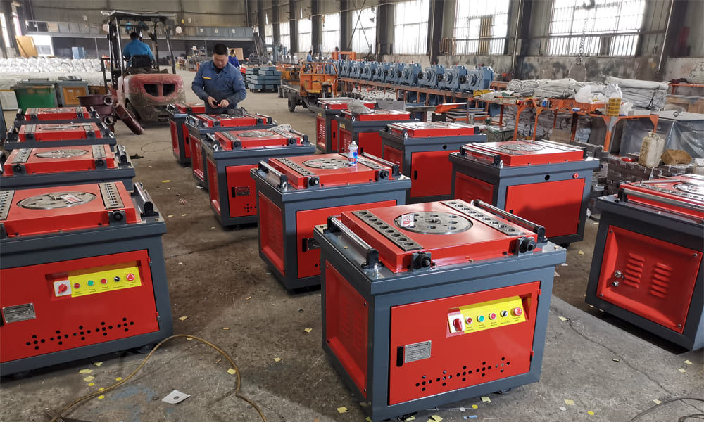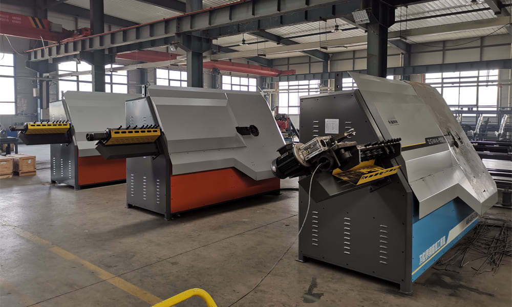
Automatic Steel Bar Bender Cutter Machine Overview
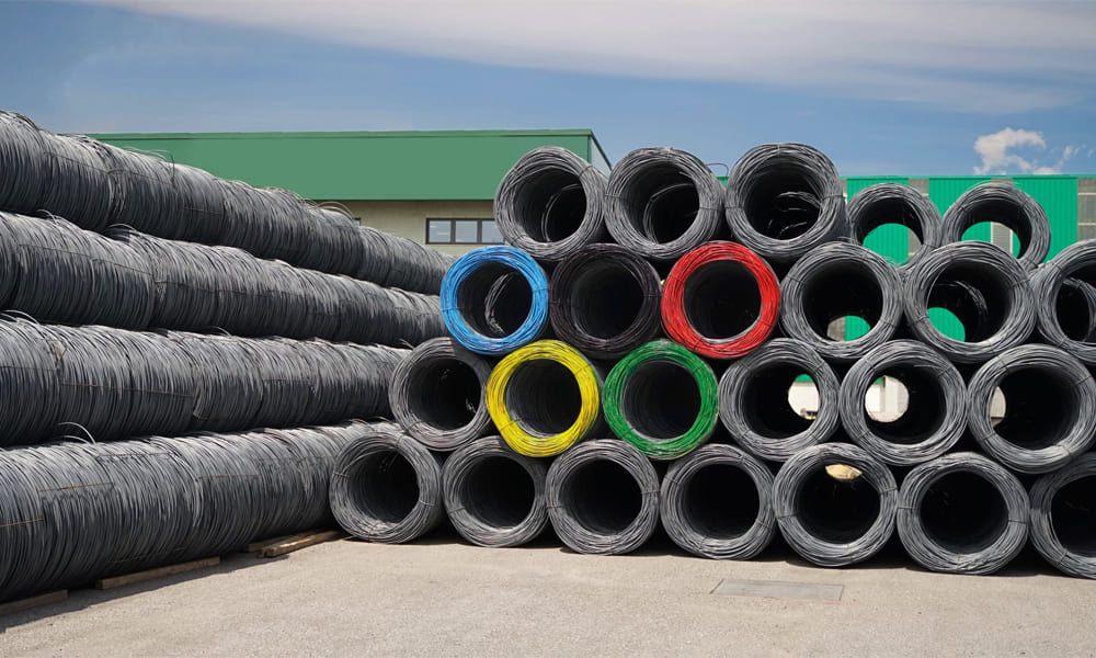
Automatic Steel Bar Bender Cutter Machine is designed for high-efficiency processing of various types of steel bars, including cold-rolled ribbed steel, hot-rolled third-grade steel, plain round steel, and non-ferrous round materials. It handles diameters ranging from 4 to 12 mm, with some models accommodating up to 16 mm. This machine excels in producing stirrups for cement prefabricated component factories, cement products factories, construction sites, steel markets, and similar units.
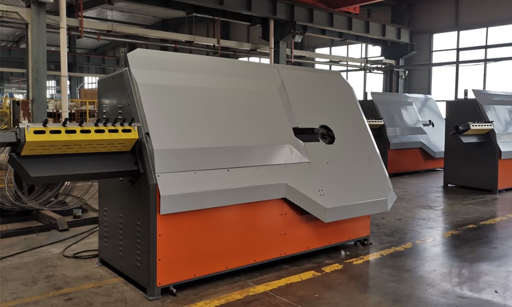
Structure and Composition
- Straightening Part:
- Composed of 24 straightening rollers driven by a motor V-belt pulley transmission system and a reducer.
- Includes 12 upper and lower rollers and 12 horizontal rollers to achieve effective straightening through adjustable rolling reduction.
- Shearing Part:
- Powered by a 4kW electric motor.
- Features a cutting device at the front end of the bending stirrup, synchronized with the bending operation via a travel switch signal.
- Electrical Control Device:
- Includes straightening motor, bending hoop motor, hydraulic system motor, solenoid valve, console, length control travel switch, and circuit components.
- Main electrical specifications:
- Power supply: Three-phase AC, 50HZ, 380V
- Control power supply voltage: 220V
- Straightening servo motor: 21kW
- Bending hoop servo motor: 7.5kW
- Shearing hydraulic motor: 4kW
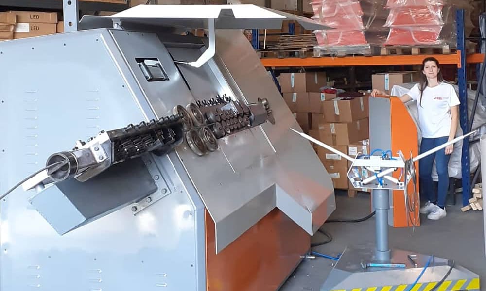
Working Principle
- Machine Structure:
- Includes machine base, pre-adjustment, traction mechanism, straightening frame, hydraulic cutting mechanism, automatic meter counting device, bending device, bearing frame, traveling device, and PLC electrical control.
- Pre-Adjusting Part:
- Straightens the wire through pre-adjusting wheels for optimal entry into the straightening barrel.
- Adjustment Cabinet Part:
- Adjusts the straightening wheel to achieve the required eccentricity and completes the straightening in the high-speed rotating straightening cylinder.
- Traction Part:
- Driven by a servo motor, it uses a reducer mechanism to pull the wire forward for entry and exit.
- Meter Counting Device:
- Electronically controlled length measuring device sets and counts the wire length via a CNC screen and sensor. It triggers shearing when the set length is reached.
- Cutting Part:
- Powered by a motor, it drives a mechanical cutting mechanism through a reducer to cut the wire, which resets after each cycle.
- Bending Part:
- Driven by a servo motor through a reducer to rotate the eccentric disk for precise bending. It resets for the next cycle.
- Bearing Frame Part:
- Guides the wire after cutting and bending, allowing it to slide down automatically after reaching the specified length.
Precautions
- Avoid reversing the bending part. The bending and straightening parts are connected in parallel. Verify the correct rotation direction by pressing the forward button on the straightening machine. If incorrect, adjust the phase connections of the three-phase power supply.
Installation and Debugging
- Activate Console Power:
- Start by turning on the console’s power supply.
- Switch on Host Power:
- Ensure the host power is correctly activated.
- Verify Cable Connections:
- Check the sequence of host cables and ensure the cutter does not obstruct the rebar exit. Adjust wire openings if needed.
- Adjust Large and Small Wheels:
- Use the remote control to adjust the wheels for steel bar insertion. Loosen and tighten as required.
- Position and Align Steel Bars:
- Feed the steel bar under the big wheel, adjust it by clicking the big wheel, and align with the cutting knife.
- Adjust Parameters:
- Set return parameters with the knob and start the process.
- Test Functionality:
- Test with a single steel bar using automatic graphic modulation. Verify proper stirrup production.
- Switch to Continuous Modulation:
- Once successful with single stirrup production, switch to continuous modulation and start for consistent stirrup output.