Hydraulic Rebar Spiral Bender
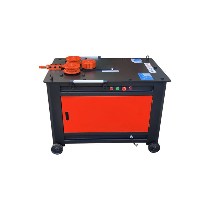
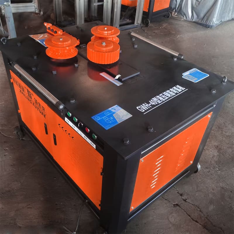
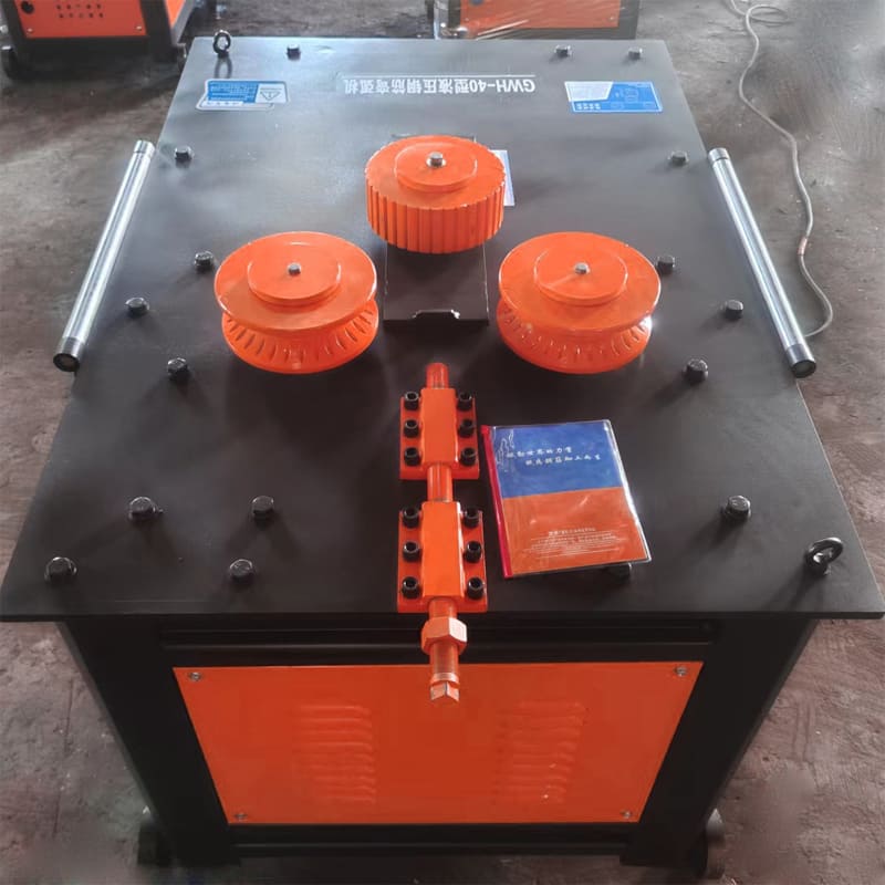
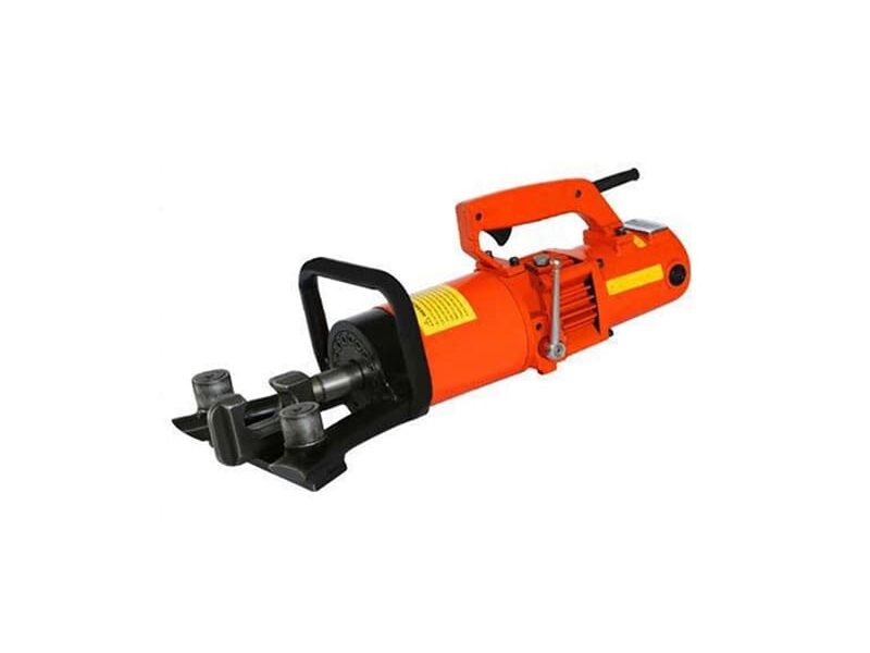
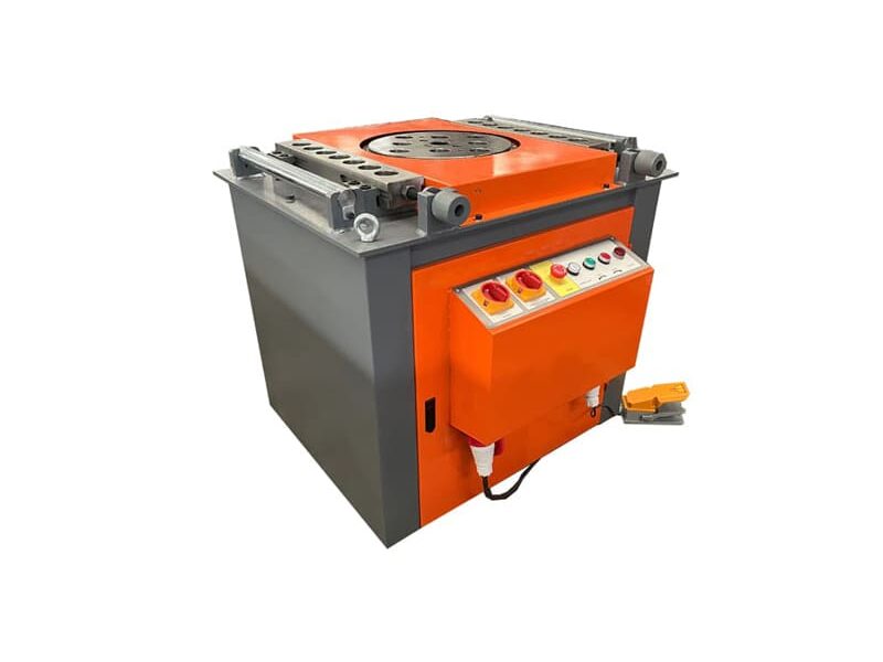
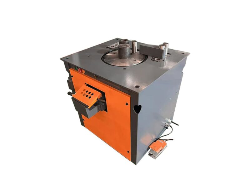
Hydraulic Rebar Spiral Bender is a mechanical device designed to bend steel bars into circular or spiral shapes efficiently, particularly suited for larger steel bars. It operates using a hydraulic system controlled by electronic technology to facilitate automated, precise production. This machine requires minimal manpower, enhances production efficiency, and reduces overall costs.
Technical Parameters
| Specification | Details |
| Round Plain Bar Capacity | 14 – 32 mm |
| Deformed Bar Capacity | 14 – 30 mm |
| Motor Power | 4 kW |
| Motor Speed | 1440 r/min |
| Rated Voltage | 380 V |
| Spiral Bending Speed | 28 r/min |
| Vernier Scale | 1 cm = 1.5 m |
| Dimensions | 1100 x 800 x 850 mm |
| Machine Weight | 380 kg |
| Panel Thickness | 12 mm |
| Spiral Bending Diameter Range | |
| – Ø16 | Minimum: 0.3 m, Maximum: Unlimited |
| – Ø18 | Minimum: 0.4 m, Maximum: Unlimited |
| – Ø20 | Minimum: 0.4 m, Maximum: Unlimited |
| – Ø22 | Minimum: 0.4 m, Maximum: Unlimited |
| – Ø25 | Minimum: 0.4 m, Maximum: Unlimited |
| – Ø28 | Minimum: 0.5 m, Maximum: Unlimited |
| – Ø32 | Minimum: 0.6 m, Maximum: Unlimited |
Working Principle
The machine functions by presetting the bending angles and arcs through mechanical and control systems, allowing automatic bending of steel bars. Key components include:
- Driving and Passive Wheels: Steel bars are placed at the feed port, with the distance between the wheels adjusted according to bar size. The active wheel feeds in the steel bar, enabling quick, precise bending.
- Multiple Bending Molds: Equipped with interchangeable molds, the machine can handle various diameters and shapes, adapting to different bending requirements.
- Control System: Ensures accurate control of bending angles and speed for precision and efficiency.
Application Fields
Hydraulic steel bar bending machines are widely used in:
- Construction of Infrastructure: Essential for projects like buildings, bridges, and tunnels, these machines bend steel bars into required circular or spiral shapes.
- Bridge Construction: Bends steel bars into complex shapes to meet specific structural demands in bridge frameworks.
Operation and Maintenance Guide
For safe and efficient use, follow these operation and maintenance steps:
- Mechanical Checks:
- Confirm that the machine’s mechanical properties are in good condition and that the workbench is level.
- Mold Installation:
- Set up the mandrel, forming shaft, iron stop shaft, or variable stop frame based on the steel bar diameter and bending requirements.
- The mandrel diameter should generally be 2.5 times the steel bar diameter for optimal bending.
- Safety Inspection:
- Inspect the mandrel, stopper, and turntable for any damage or cracks, and ensure the protective cover is securely fastened.
- Run the machine empty first to verify normal operation before beginning.
- Operation Specifications:
- Insert the end of the steel bar into the turntable gap and fix the other end against the machine body, holding it tightly by hand.
- Before starting, ensure the machine body is positioned to block the steel bar.
- Important: Do not replace the mandrel, adjust the angle, or change speed settings during operation.
