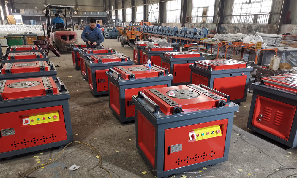
P52 Steel Bar Bender is a core device in steel bar processing. Essentially, it uses mechanical transmission to drive its working mechanism and applies directional bending moment to steel bars. This allows workers to bend the bars into specific angles or shapes—such as stirrups and hooks—per construction requirements. Additionally, it is widely used in various engineering scenarios, including construction and bridge projects.
I. Basic Working Principle
In simple terms, P52 Steel Bar Bender follows this working logic: the motor provides power, the transmission system adjusts speed and torque, the working disk drives accessories to extrude the steel bar, and finally the steel bar undergoes plastic deformation. Specifically, the process unfolds as follows:
-
Power Input: When the motor starts, it generates rotational power. It then transmits this power to the reduction mechanism via a coupling.
-
Speed Reduction and Torque Increase: Motors typically run at high speeds but produce low torque—this is insufficient for bending steel bars. Therefore, a gear reducer is used to lower the speed while boosting torque, ensuring enough force to drive the working disk.
-
Steel Bar Positioning and Fixing: First, place the steel bar to be processed between the working disk’s forming shaft and material stop shaft. Then adjust the mandrel’s position so the bar fits tightly against its surface—this guarantees the accuracy of the bending radius.
-
Bending Forming: The transmission system drives the working disk to rotate in a circular motion, which in turn drives the forming shaft to spin synchronously. As the forming shaft rotates, it applies continuous bending moment to the steel bar. Meanwhile, the material stop shaft restricts the bar’s radial movement to prevent slipping. Under this bending moment, the steel bar undergoes plastic deformation. Once the working disk rotates to the preset angle, the motor stops, and a single bending operation is complete.
-
Reset and Unloading: The motor then reverses to move the working disk back to its initial position. After that, the operator can easily take out the bent steel bar.
II. Core Structural Composition and Coordination Mechanism
A P52 Steel Bar Bender consists of several core components, including a motor, gear transmission system, working disk, mandrel (forming shaft), material stop shaft, and machine body/frame. All these parts work in tandem to complete the bending process. Below is a detailed breakdown of each component’s functions and how they coordinate with one another:
|
Core Components
|
Structural Characteristics
|
Functional Roles
|
Coordination with Other Components
|
|---|---|---|---|
|
Motor
|
Mostly three-phase asynchronous motors, with power ranging from 1.5kW to 7.5kW depending on the model (small desktop / large vertical)
|
Provides the power source for the operation of the entire machine
|
Its output shaft connects to the gear reducer’s input end via a coupling, supplying initial power to the transmission system. Moreover, it uses a control circuit to achieve positive and negative rotation, which meets the working disk’s rotation and reset needs.
|
|
Gear Transmission System
|
Composed of a reducer, driving gear, driven gear, etc. The gears are forged from high-strength alloy steel, and the tooth surface is quenched
|
Reduces speed and increases torque, converting the high-speed and low-torque of the motor into the low-speed and high-torque required by the working disk
|
The driving gear links to the motor’s output end, while the driven gear connects to the working disk’s main shaft. Power transfers through gear meshing, ensuring the working disk rotates stably with sufficient torque.
|
|
Working Disk
|
Circular disk structure, made of cast iron or cast steel, with multiple adjustment holes on the disk surface for installing mandrel and material stop shaft
|
Carries and drives the forming accessories to operate, and is the executive mechanism of the bending operation
|
It connects coaxially to the gear transmission system’s driven gear and rotates under the gear’s drive. Additionally, the holes on the disk allow adjustments to the distance between the mandrel and material stop shaft, making it suitable for bending steel bars of different diameters (φ6 – φ40mm).
|
|
Mandrel (Forming Shaft)
|
Cylindrical structure with smooth surface, made of high-carbon steel, and can be replaced with different diameter specifications
|
Determines the bending radius of the steel bar and is the benchmark component for steel bar bending
|
Workers install it in the working disk’s adjustment hole, so it rotates synchronously with the disk. During bending, the steel bar clings tightly to the mandrel’s surface. Notably, the mandrel’s diameter determines the bar’s minimum bending radius, which must comply with steel bar processing specifications.
|
|
Material Stop Shaft
|
Fixed on the machine body or the edge of the working disk, with height matching the mandrel
|
Limits the displacement of the steel bar and prevents the steel bar from slipping and deviating during bending
|
It works with the mandrel to clamp the steel bar, keeping the bar stable during bending. For some models, workers can adjust the material stop shaft’s height and position, allowing it to adapt to bending operations at different angles.
|
|
Machine Body and Frame
|
Welded by section steel, with anchor bolt holes at the bottom
|
Carries all components and ensures the stability of the entire machine
|
It secures core components like the motor, gearbox, and working disk. It also disperses the impact force generated during bending. Furthermore, anchor bolts can fix the frame to the ground, preventing the equipment from shaking during operation.
|
III. Key Coordination Points of Core Components
-
Continuity of Power Transmission: First, the power transmission path—from motor to coupling, then to gearbox, and finally to working disk—must be free of jams. Workers also need to accurately control the gear meshing gap; this avoids power loss and equipment noise.
-
Accuracy of Positioning Components: Workers must adjust the distance between the mandrel and material stop shaft based on the steel bar’s diameter. If the distance is too large, the bar may slip. Conversely, a too-small distance will increase bending resistance and even damage the bar’s surface.
-
Matching of Control System: The motor’s positive/negative rotation control and speed adjustment must align accurately with the working disk’s rotation angle. To ensure consistent batch processing, travel switches or CNC systems achieve angle positioning—for example, 90° and 135° hooks.